
Proof of concept
I prove designs end to end before they go anywhere near a live network. Routing changes, firewall policy and failover all get tested here first.
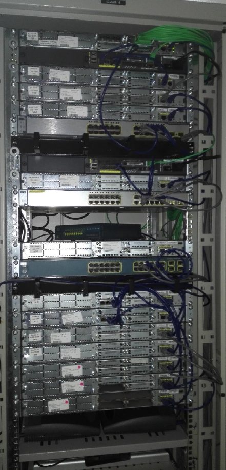
I am Punit, a senior infrastructure and network architect, and this is my Cisco home lab. I use it for proof of concept work, troubleshooting and certification study. Every Cisco router, switch, IP phone and access point, and every HP server, is physical kit.

I am an infrastructure and network architect with more than 20 years of hands on delivery across manufacturing, industrial software, telecoms, financial services and consulting. I act as technical design authority from discovery through to handover.
For manufacturers such as Dyson and Weetabix I design IT and OT (operational technology) convergence: Purdue Model zoning, OT security and secure data paths from the plant floor to the cloud. Underneath sits deep network, security and multi cloud architecture across Cisco, Palo Alto, AWS (Amazon Web Services), Azure and Google Cloud.
I hold AWS Solutions Architect Professional, CCNP (Cisco Certified Network Professional) Enterprise and CCDP (Cisco Certified Design Professional), and I have passed the CCIE (Cisco Certified Internetwork Expert) Security and Routing and Switching written exams. This site is independent and technical: my lab, and the knowledge behind my work.
I wanted a place where I can run a real enterprise network end to end, on physical hardware, without putting anything live at risk.
I prove designs end to end before they go anywhere near a live network. Routing changes, firewall policy and failover all get tested here first.
When a fault is hard to pin down, I rebuild the scenario here. I can break things on purpose and work through the fix with no risk to anyone.
The lab covers routing, switching, security, voice, wireless and virtualisation. It has been my study bench for Cisco and VMware certifications.
The lab models a company called ITS Ltd with offices in London, New York and Dubai. A second company, GAP Ltd, shares the same carrier network from Perth and Sydney. Every ITS Ltd office has two ways out: a private MPLS (Multiprotocol Label Switching) link as the main path, and an internet link as the backup.
A simplified view I drew from the full diagram further down. The subnets match the real build.
Swipe sideways to see the whole diagram.
Main path. Traffic between the three ITS Ltd offices runs over MPLS. The PE (provider edge) routers keep each customer's routes in its own VRF (virtual routing and forwarding table). The P (provider core) routers in the middle only switch labels, so they never need to know a customer route.
Backup path. Here the link between London's CE (customer edge) and PE routers has failed, so London loses its MPLS route. Its traffic now leaves through the edge firewall and internet router, and reaches New York through a DMVPN (Dynamic Multipoint VPN) tunnel across the simulated internet. The dashed line is the tunnel. Underneath, the packets cross the terminal server like any internet traffic. When the link comes back, MPLS takes over again.
Internet access. Each office goes out through its edge firewall and internet router to the simulated internet on the terminal server. The terminal server has a default route to my home network, so the lab reaches the real internet as well.
Two customers, one core. GAP Ltd sends traffic from Perth to Sydney across the same P routers that carry ITS Ltd. Each customer has its own VRF, so their routes never mix, and they could even use the same private addresses.
Management. From my home network I connect to the terminal server, then open a console session on any router or switch, even when the routing is broken. The iLO (Integrated Lights Out) ports on the three HP servers are on my home network too, so every ESXi host stays reachable.
Two P (provider core) routers and five PE (provider edge) routers act as the carrier. Each customer gets its own VRF (virtual routing and forwarding table), so ITS Ltd and GAP Ltd share the core but never see each other's routes.
Each site has an edge firewall and its own internet router. If the MPLS path fails, traffic moves to DMVPN (Dynamic Multipoint VPN) tunnels built across the internet between the three sites.
The terminal server, a Cisco 2811, uses VRFs to act as a public internet between the sites. A default route to my BT Infinity line, through a DrayTek router, gives the lab real internet access too.
The terminal server gives me console access to the kit. The iLO (Integrated Lights Out) ports on the HP servers sit on my home network, 192.168.1.0/24, so I can always reach every host.
The detailed build diagram, with every interface and subnet. Open it full size and click to zoom in.
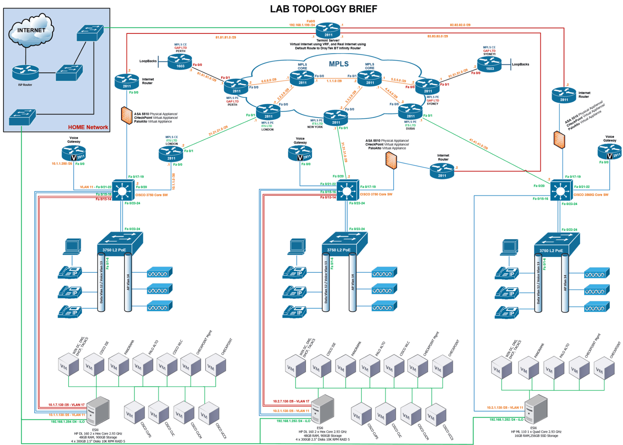
Top left. My BT Infinity broadband and home switches. It feeds real internet into the lab and carries the iLO network for all three servers.
Top centre. A Cisco 2811 on 192.168.1.199. It runs the simulated internet with VRFs and links to each site's internet router on its own /29.
Centre. Two P routers joined on 1.1.1.0/29, and five PE routers for Perth, London, New York, Dubai and Sydney. All are Cisco 2811s.
London connects through a CE (customer edge) router. In New York and Dubai the core switch connects straight to the PE. GAP Ltd uses Cisco 1603 CE routers with loopbacks.
Each site has a layer 3 core switch, a layer 2 PoE (Power over Ethernet) access switch on two uplinks, a voice gateway, three IP phones, three access points and a PC.
One VMware ESXi host per site. London and New York run HP DL160s with 11 VMs each, including the full Cisco voice suite. Dubai runs a smaller HP ML110 with 5 VMs.
Nine areas I can build, test and break on demand, all on the same network.
A carrier style core with P, PE and CE roles. Two customers share it in separate VRFs, so I can test VPN design, customer separation and convergence.
Every site has MPLS as the main path and DMVPN over the internet as the backup. I can pull a link and watch failover and failback happen for real.
VRFs on the terminal server act as a public internet between the sites. A default route to my BT line adds real internet access when I need it.
The edge at each site can run a physical Cisco ASA 5510, a virtual Check Point or a virtual Palo Alto. Check Point management and Panorama give central policy control.
Layer 3 core switches route between VLANs. Layer 2 PoE access switches power the phones and access points, with two uplinks back to the core.
A multi site voice build with call control, voicemail, presence and a contact centre. Every site has a voice gateway and three IP phones.
Three access points per site on their own VLAN, managed by a virtual Cisco WLC (Wireless LAN Controller).
Cisco ISE (Identity Services Engine) for network access control. Windows Server 2012 R2 runs Active Directory, DNS, DHCP and TACACS for device logins.
VMware ESXi on three HP servers, managed through vCenter, with vMotion to move running VMs between hosts. iLO gives remote console access.
Every ITS Ltd site uses the same port plan and VLAN numbers. Only the WAN handoff and the server size change. That keeps changes repeatable and makes faults easy to compare.
21.21.21.0/2981.81.81.0/29192.168.1.25431.31.31.0/2983.83.83.0/29192.168.1.25341.41.41.0/2982.82.82.0/29192.168.1.252A branch style site. It has no call servers of its own, so its phones rely on the call managers in London and New York.
GAP Ltd has CE routers in Perth and Sydney, both Cisco 1603s, with loopback interfaces standing in for office networks. It shares the MPLS core with ITS Ltd but lives in its own VRF. That lets me prove the two customers stay apart while sharing the same carrier routers.
Show in the diagramFor anyone who wants to check the design: VLANs, addressing, WAN links, the port plan and the compute behind each site.
| VLAN | Purpose | Where it lives |
|---|---|---|
| 11 | Servers and voice gateway | Core switch, ESXi host, voice gateway |
| 12 | Data | PCs on access ports Fa0/1 to 0/6 |
| 13 | Voice | IP phones on access ports Fa0/1 to 0/6 |
| 14 | Wireless access points | Access switch AP ports |
| 17 | Second ESXi network (vMotion) | Core switch to ESXi host, London and New York |
| Site | ESXi on VLAN 11 | ESXi on VLAN 17 | iLO |
|---|---|---|---|
| London | 10.1.1.130/25 | 10.1.7.130/25 | 192.168.1.254/24 |
| New York | 10.2.1.130/25 | 10.2.7.130/25 | 192.168.1.253/24 |
| Dubai | 10.3.1.130/25 | Not used | 192.168.1.252/24 |
Each site has its own 10.x range: London 10.1.x.x, New York 10.2.x.x and Dubai 10.3.x.x. The London voice gateway sits on 10.1.1.250.
| Link | Subnet | Type |
|---|---|---|
| P1 core to P2 core | 1.1.1.0/29 | Provider core |
| P1 core to PE London | 2.2.2.0/29 | Provider core |
| P2 core to PE New York | 3.3.3.0/29 | Provider core |
| P2 core to PE Dubai | 4.4.4.0/29 | Provider core |
| P2 core to PE Sydney | 5.5.5.0/29 | Provider core |
| P1 core to PE Perth | 6.6.6.0/29 | Provider core |
| PE London to CE London | 21.21.21.0/29 | ITS Ltd |
| CE London to London core switch | 10.1.1.0/30 | ITS Ltd |
| PE New York to New York core switch | 31.31.31.0/29 | ITS Ltd |
| PE Dubai to Dubai core switch | 41.41.41.0/29 | ITS Ltd |
| PE Perth to CE Perth | 61.61.61.0/29 | GAP Ltd |
| PE Sydney to CE Sydney | 51.51.51.0/29 | GAP Ltd |
| Terminal server to London internet router | 81.81.81.0/29 | Internet |
| Terminal server to Dubai internet router | 82.82.82.0/29 | Internet |
| Terminal server to New York internet router | 83.83.83.0/29 | Internet |
| Terminal server to home network | 192.168.1.199/24 | Home network |
Public style /29 ranges on the internet and provider links make the lab look and behave like a real carrier and internet path.
| Ports | Connects to |
|---|---|
| Fa0/13 to 0/14 | ESXi host on VLAN 17 (London and New York) |
| Fa0/15 to 0/16 | ESXi host on VLAN 11 |
| Fa0/17 to 0/19 | Edge firewall |
| Fa0/20 | WAN: the CE router in London, the PE router in New York and Dubai |
| Fa0/21 to 0/22 | Voice gateway |
| Fa0/23 to 0/24 | Two uplinks to the access switch |
| Ports | Connects to |
|---|---|
| Fa0/1 to 0/6 | IP phones, with a PC behind the phone (data VLAN 12, voice VLAN 13) |
| AP ports | Three access points on VLAN 14 |
| Fa0/23 to 0/24 | Two uplinks to the core switch |
| Site | Host | CPU | Memory | Storage | VMs |
|---|---|---|---|---|---|
| London | HP ProLiant DL160 | 2 × hex core 2.93 GHz | 48 GB | 900 GB: 4 × 300 GB 10K disks, RAID 5 | 11 |
| New York | HP ProLiant DL160 | 2 × hex core 2.93 GHz | 48 GB | 900 GB: 4 × 300 GB 10K disks, RAID 5 | 11 |
| Dubai | HP ProLiant ML110 | 1 × quad core 2.93 GHz | 16 GB | 256 GB SSD | 5 |
| Total | 3 hosts | 28 cores | 112 GB | About 2 TB | 27 |
| Role | Virtual machines |
|---|---|
| Core services | Windows Server 2012 R2 with Active Directory, DNS, DHCP and TACACS |
| Security | Palo Alto firewall and Panorama, Check Point firewall and management server, Cisco ISE |
| Wireless | Cisco Wireless LAN Controller |
| Voice | Cisco Unified Communications Manager (CUCM), Unity Connection (CUC), Presence (CUPS) and Contact Center Express (UCCX) |
| Management | VMware vCenter, with vMotion between hosts |
Every router, switch and server in the diagram is real hardware, racked and cabled in a single 42U cabinet. The virtual firewalls, Cisco ISE and the wireless controller run on those servers. Select any photo to see it larger.
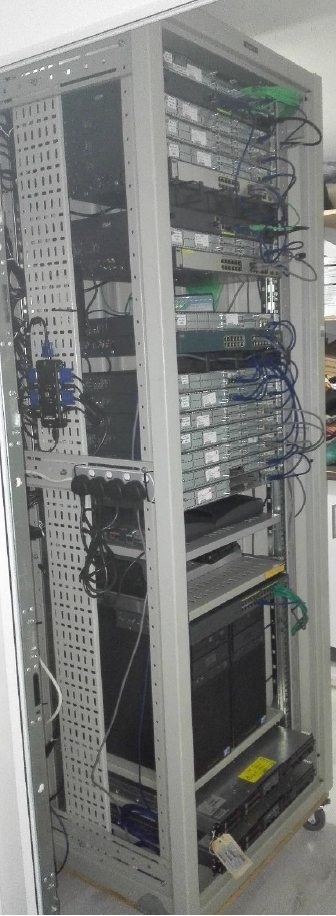
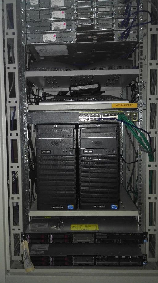
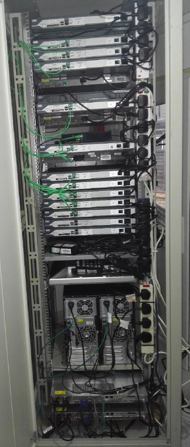
The main kit shown in the topology.
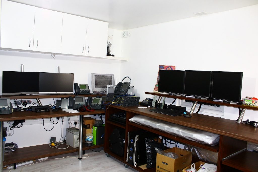
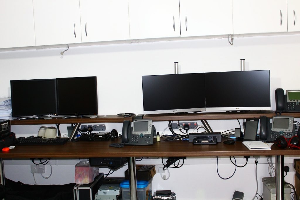
Kit gets built and configured on the bench before it goes in the rack, and spares are kept close by.
Three desks with multiple screens, IP phones on the bench and room to stage new kit. I build and test configurations here before a device goes into the rack.
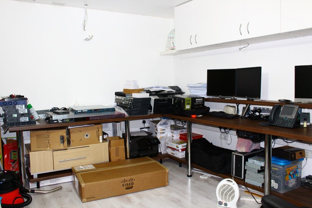
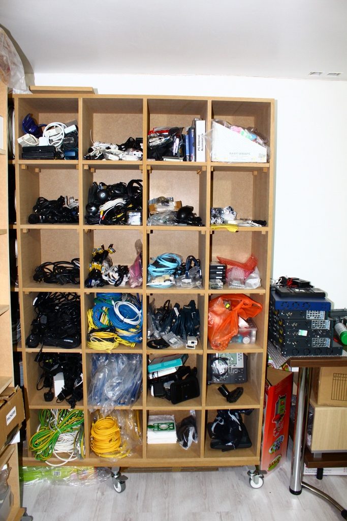
Cables, power leads, modules and spare parts, sorted by type. A rebuild never waits on a missing lead.
The lab is where I test ideas. These pages show the knowledge behind it, from the foundations to full designs, with diagrams you can step through and simulations you can try.
The basics everything else is built on: how networks move data, copper and fibre cabling, addressing, switching, routing, security and how I find faults.
WAN, campus and wireless networks, the platforms they run on, how traffic is prioritised, the security that protects them, and how I automate them.
Fabrics, Nexus switching, cabling, facilities, servers, private and public cloud, and the infrastructure behind AI.
Manufacturing plants, IoT and edge, government, financial trading, and the networks behind UK education and research.
Design authority, architecture and project frameworks, service management, and how users and their devices are supported.
Live sound, streaming and video, AV over IP and meeting rooms, how I run events, and editing afterwards.
I have led technology programmes for banks, insurers, manufacturers and the NHS. The standards I learnt there are the ones I build to in this lab, and the ones I bring to every client.




















Certifications, specialist exams and training I have completed, then put to work in this lab and on client projects.
64 listed entries12 vendor sections + specialist training
CCIE Security
Written exam
Written exam onlyCCIE Routing and Switching
Written exam
Written exam only
CCNP Enterprise
Enterprise networking
Credential listed
CCNP Routing and Switching
Routing and switching
Credential listedCCDP ARCH
Network design
Credential listed
CCNA Routing and Switching
Routing and switching
Credential listedCCVP
Voice, later renamed CCNP Voice
LegacyCCIP
Service provider
Legacy

Microsoft Azure
Cloud platform
TrainedMCITP and MCSE
Microsoft server infrastructure
Legacy
Solutions Architect Professional
AWS Certified
Credential listed
Google Cloud Platform
Cloud platform
TrainedVMware Certified Professional
VCP5, Data Centre Virtualisation
Credential listed



Building Technologies
Honeywell
Trained
Home and Building Automation
Control4
TrainedBuilding Management Systems
BMS
TrainedHeating, Ventilation and Air Conditioning
HVAC
TrainedOperational Technology
OT
TrainedPower and Electrical
Site power
TrainedFibre and Copper Cabling
Structured cabling
Trained

PRINCE2
Programme and project governance
FrameworkITIL v3 and v4
Service management
FrameworkTM Forum Architecture
Telecoms frameworks
FrameworkEnterprise Security
Regulatory and security frameworks
FrameworkSC Clearance Eligible
United Kingdom
EligibleLabels reflect the reference, not verified current status.